
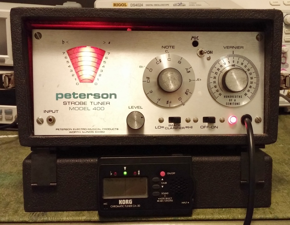
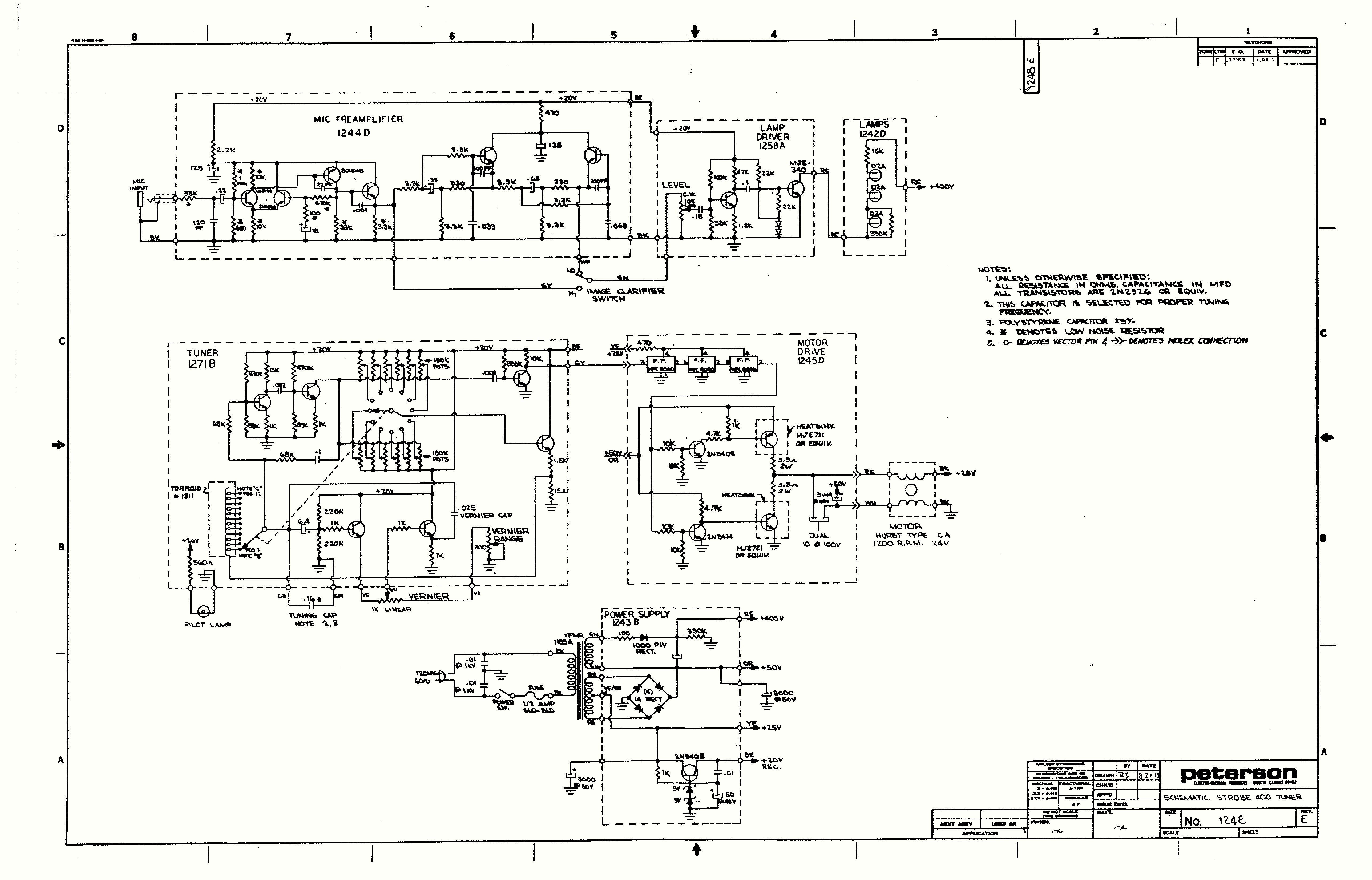
Refurbishing a Strobe Tuner
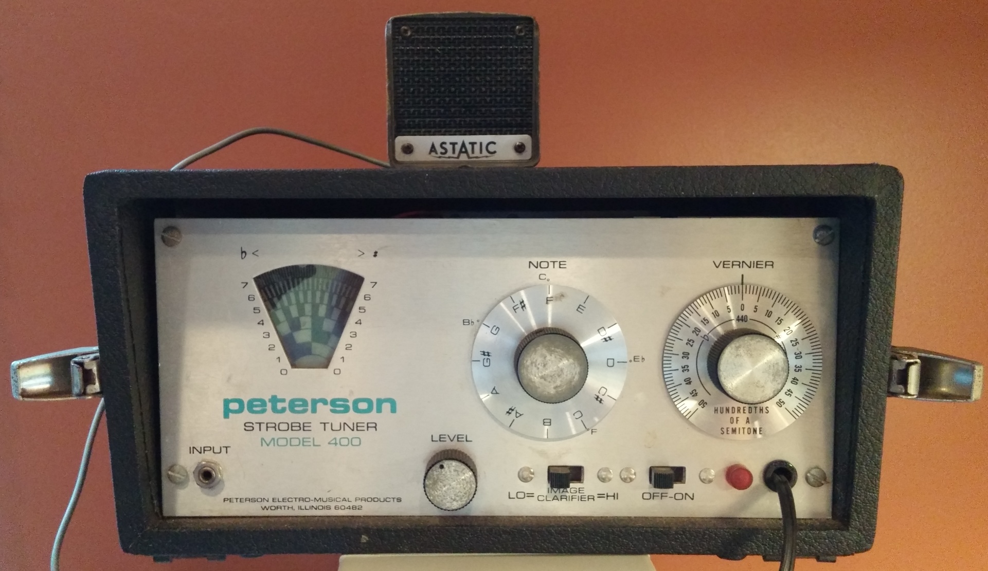
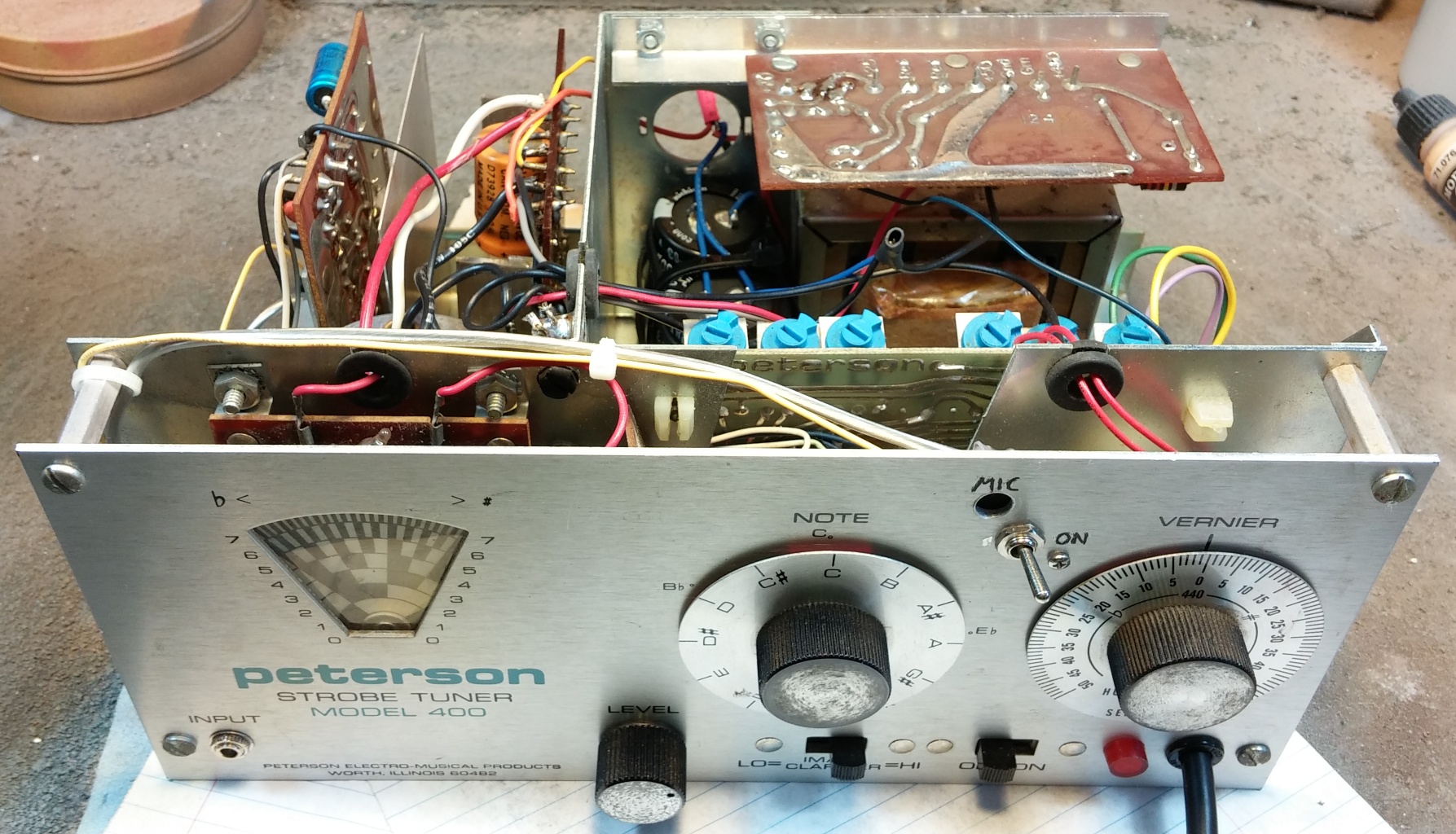
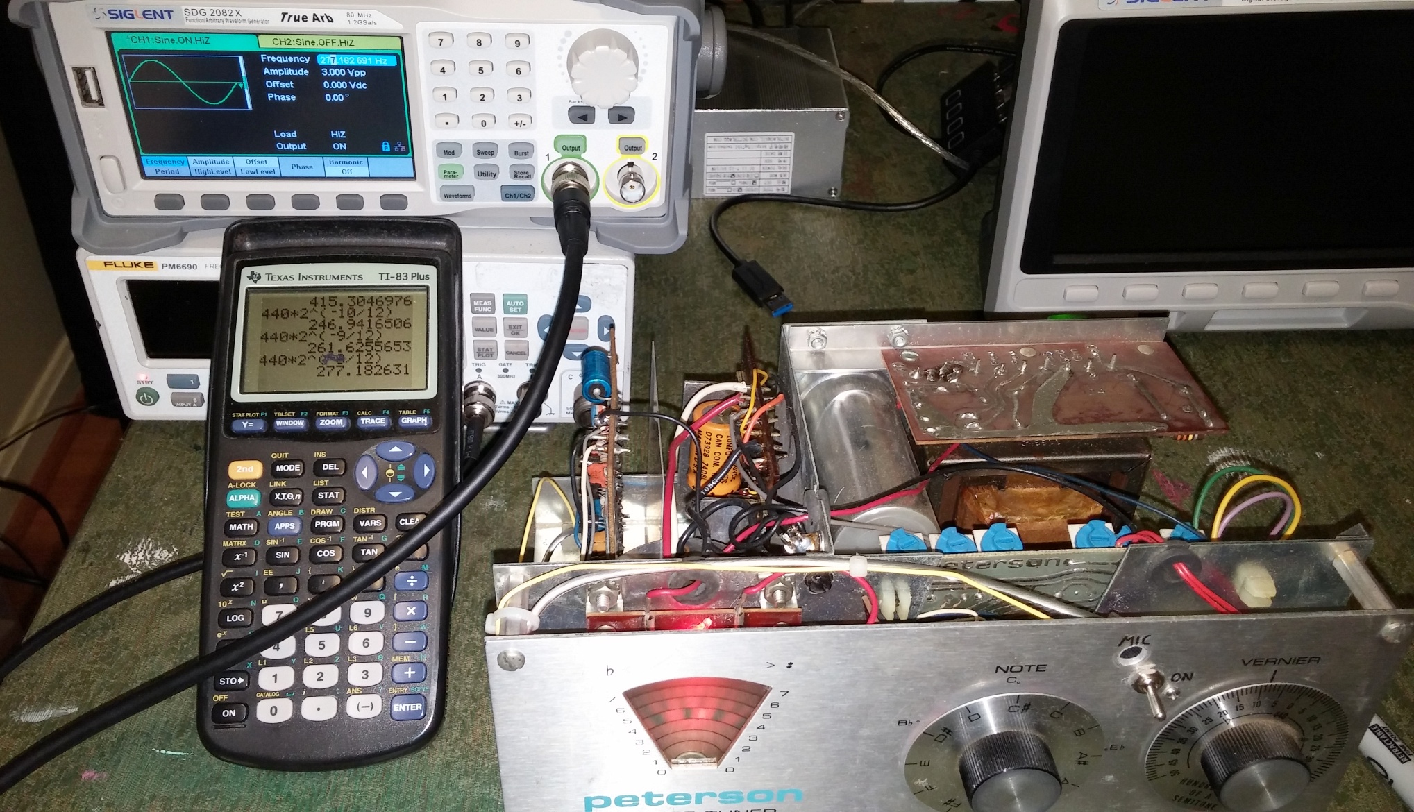
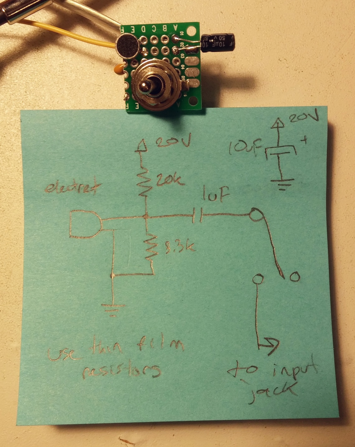
First, you feed a reference tone into the input. A simple sine wave will do, but any completely stable, completely accurate signal will work, and work out the math for the frequency of each with this formula: frequency = reference tone * 2 ^ (half steps from A / 12). The reference the machine states is A = 440 Hz, and the number of half steps can be positive or negative, the resulting number will be different, but the pitch will be the same, just in different octaves.
/*
back to top */
-
Distribution Amplifier
-

The old medpants.com
-
PondMaster Robot
-
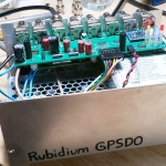
Rubidium GPSDO
